 The LM3886 stereo chip amp module(one chip per chanel), next to the Malaysian RM$0.50 sen coin for scale.
The LM series chip amp modules are designed for driving plasma or LCD TV speakers. Their design brief was simple, make em' small, light and cheap. There are a series of LM chips available with various power out put and specs. Here are 3 popular ones, like LM3875, LM 3886 and LM4780. A few years ago, some DIYers saw hifi potential in the chip modules and started building them with surprisingly great sonic results. The buzz generated even caused some of the high end manufacturers to take notice. I think Jeff Rowland and Bel Canto are just 2 of the more famous brands manufacturing power amps using paralleled LM series chip module.
 Amp in a chip. If using single ended one chip contains one chanel of amplification. The LM series chip is made by National Semicon.
I started my chip amp project some time in 2008. Since I have many DIYer friends who have already built various examples of the above 3 popular LM chip modules from various kits, all I have to do is to go around and listen to their finished projects and select the chip module that I liked most. After a bout of auditioning, here is my conclusion in general to the sound of each LM chip module.
LM3875: Very powerful and dynamic sound that belies it's 35W RMS rated power out put. Tonality is dead neutral, with little warmth in the music.
LM3886: Sounds less powerful and dynamic compared to the above chip module, as it should with only 34W RMS available(This is where the first watt theory comes in? He!, He!, ask DIYer Papa Nelson Pass). But makes up for it with a warmer tonal palette that's unfailingly musical.
LM4780: Gives double the power out put of LM3886. It has the same warm tonal palette but the musicality and transparency factor is slightly compromised somewhat. If you have a power hungry speaker to drive or a big room to fill with sound, this has to be your choice.
 I bought standard available heat sinks from the nearest friendly electronics store. Heat sink size is important and is based on the voltage rail one intend to use for the LM3886. Again too big a heat sink and the amp doesn't sound good, as the chip amp modules need a bit of load to work well. Too small a heat sink will cause the LM module to shut down temporairly or burn it self out in most extreme cases like a direct short. I know, because I burnt a pair of LM3886 chips while testing! Thank goodness they are easily available and a dime a dozen. They cost about RM$60.00 per chip at http://my.farnell.com/.
 I fabricated a mounting L bar from stainless steel to mount the ML3886 chip amp module and used one heat sink per chip. You may choose to share a heat sink for both chips if so wished.
 The final amplification module assembly.
Like all LM series chip amp module, power supply scheme plays a very important role to the final sound. Apparently on some kits that I've seen, the power supply module is more complex than the LM chip module in it self!
I bought the 2 pcs LM3886 chip amp module from http://diyclub.biz/ (again?) as I know them and I was in Hong Kong for a business trip. So it's rather out of convenience than anything else! Actually, you only need one stereo chip module to build single ended topology. Being the balanced fella that I am, I used one stereo chip module per chanel. I used one chanel for the positive signal and another for the negative signal, with the common ground wired as per the standard XLR, pin 2 positive requirement.
 The 24V @ 4 ampere rated power trans. I used one transformer for each LM3886 module.
 The standard transformer with center tap, I used replecement rubber gromet for water taps to mount under the transformer for some form of vibration control.
I used an over sized 24V @ 4 ampere rated power transformer for each stereo chip amp module.(remember the power supply does make a difference! I've also seen a friend specified a 18V @ 10 ampere power trans for his LM3875, that's 10X the specified requirement.) Due to the need to fit the space constraint of an A-28 case, again sourced from diyclub, I only used 4X the spec requirement, which is still plenty. I scratch built power supply board for each LM chip module, by having a bridge rectifier, and 40,000uf storage/filtering caps per LM chip module(using 4 x 10,000uf @50V Panasonic KAP capacitors). Also note that during the case internal layout the power supply module must be no more than 3 inches away from the LM chip module. Having the power supply board too far away will render them non effective or at worst, allowing noise to pick up! Just as I found out during my first assembly and test stage at the end of 2008. I encountered a hum for the left chanel, when the amp was used in RCA, single ended connection, due to a lack of balanced(XLR) out put from my friend's pre amp. In balanced, XLR mode connection in my system, I did not encountered any noise problem what so ever. I left the project idle since then as I did not have the time to continue with it.
 The bridge rectifier. I used 8 ampere rated ones. There's a rule about doubling the spec to ensure long term reliabilty.
 The 10,000uf @ 50V rated Panasonic KAP capasitors for 24V voltage rail.
 The finished power supply assembly board, I've calculated the 24V voltage rail would give the LM3886 chip amp module nearly 26db of gain factor. The LM series chip amp modules can operate from a range as low 18V - 28V high. The voltage rail used will determine the gain factor of the chip amp module.
One year later, Christmas holidays 2009, I re-looked in to the project and found that by improving the case internal lay out, I could eliminate the left chanel single ended hum.(I some how always return to the warmth of the soldering gun in my hand feel every Christmas!, well at least in the last few years that is) I set about to take apart the power amp project and re-build with new internal lay out. All pictures shown are the improved final 2009 version as I did not document my earlier work. The actual rebuild work took a few days to do in between stuff once the lay out was finalised. If there's one thing I'd really wanna do is to replace all those standard single core cables in the low level signal with the vdH SCS variety as I did in my pre amp. Believe me, the vdH SCS internal cabling are worth the $$$, but how much improvement in the power amp area is what I am not able to speculate.
 The final test lay out before screwing every thing in place. I opted for a full dual mono lay out with balanced topology.
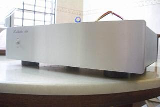 The standard A-28 case front aluminium face plate.
 The rear panel from left, RCA(single ended), XLR(balanced) input, speaker out put and IEC power input.
As expected, the finished power amp sounds warm, musically balanced and reasonably powerful to boot. Operating in Quasi class A, the LM3886 does have that sonic signature quite similar to my full class A Pass Aleph 0. When mated to the DIY 6H30 tube pre amp I wrote about last month, and powering my Audio Physic Spark speakers(which are an easy load), I heard less than fully developed timbre and harmonics, somewhat less transparency and less powerful bass delivery, compared to my usual reference system. But then, that's not a fair assessment either, as my Pass X2.5 and Aleph 0 amps cost many, many times more to buy! (not to mention, they are products of hifi industry DIYer Papa Nelson Pass!) However, if no comparison with high end equipment and viewed in their own capabilities, I'd say my DIY built amps are fair value for money.
 The finished amp in used with Wireworld Eclipse XLR interconnect and Siltech 330L speaker cable.
I loaned the finished unit to a friend to power his Dynaudio Contour 1.1 speakers and he was quite surprised by the very decent sound he could had with just 34W RMS. He is used to 100W amps by the way, which he recently sold to make way for an up grade that's yet to arrive. But he too remarked that the XLR input did sounded quieter with lower noise floor, had more drive and better dynamics to power the Dynaudio's with that much more confidence.(pun intended!)
 With the top cover on, the heat sink runs warm, which is O.K.
Since I am expecting people to ask me the cost of building this power amp? It's surprisingly cheap at RM$1,200 based total parts cost only. I would speculate that one can probably build the single ended version for roughly half the out lay, if XLR input is not important. That's because the power amp has none of those exotic, super expensive parts! The LM series chip amp modules are easy to build and will make great starter kits for those wanting to dabble in DIY but not quite built up the confidence yet. There are many, many help and design improvement threads all over the DIY forums on the www. All one has to do is Google or Yahoo search and I am pretty sure you find a lot of information pertaining the chip amp modules.
This is my last DIY project in the pipeline for now, at least until I get all itchy solder hands again. Maybe, till Christmas comes round again? Who knows!
5 comments:
Big E, Special caps? How come yr caps has fonts backwards? :-)
Felix,
Panasonic made those "special edition" reversed fonts caps for me only! Would you like to secure some? It's gonna cost ya quite abit! Ha!Ha!
Actually, it's just my photo editor software doing it's thang! Thanks for pointing out. I've corrected the pics.
Regards,
Any particular reason used 4 pieces of 10,000 uf capacitors? Other than for that big power reserve? There is also 12,000 uf values, 15,000 uf, & 18,000 uf values too.
Unker Vic,
No particular reason what so ever. I just used as big caps that I can that is tall enough to fit in to the A-28 casing. More about practical consirations than sound.
The cap are more like a resevoir storage of DC charge only. And for the LM series chip amp modules, 40,000uf is plenty already. But one can also be a bit more greedy with bigger caps I supposed.
I could've used a series of smaller caps like what you did for your amp too, but that would main more complicated power supply board build. I just like to keep thing neat and simple, that's all.
U can't used my design for chip based amps, not suitable.
Post a Comment